Indoor flying
System Architecture
In order to start flying the quadcopter indoor, we need the position and orientation feedback for this.
This section will guide you how to use OptiTrack Motion Capture System, how to stream position and orientation data to ROS, and feed it to your flight controller. Finally you will be able to fly your drone inside the arena in position mode.
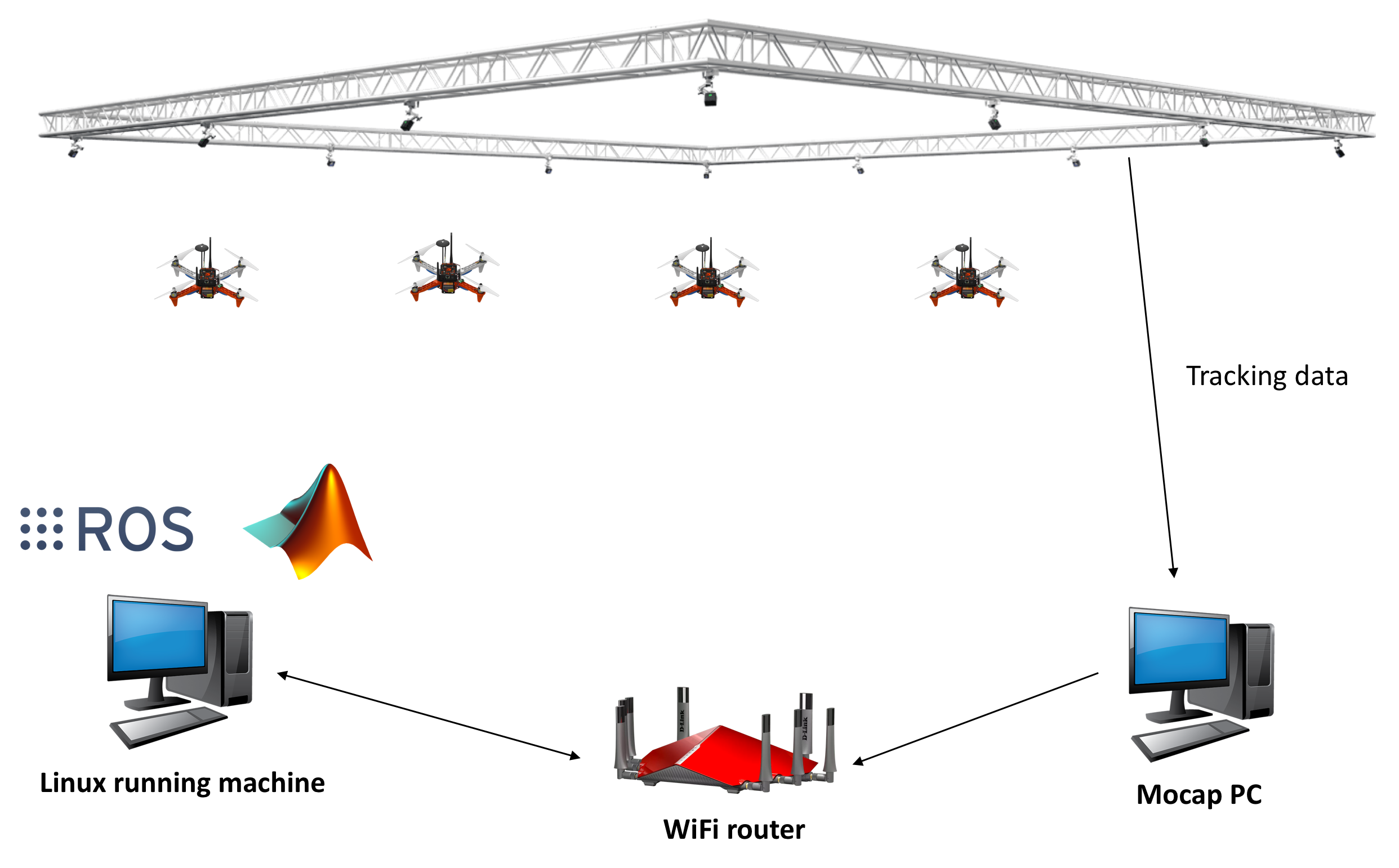
The overall systems has following main elements:
- OptiTrack Motion Capture System
- Object to be tracker, eg. quadcopter, ground vehicles.
- Controller
Let’s discuss each element in details
Motion capture system
OptiTrack motion capture system (Mocap hereinafter) works as follows. The overhead cameras send out pulsed infrared light using the attached infrared LEDs, which will then be reflected by markers on the object and detected by the OptiTrack cameras. Knowing the position of those markers in perspective of several cameras, the actual 3D position of the markers in the room can be calculated using triangulation. Simply Mocap provides high precision indoor local position and orientation estimation. Position is meters and orientation is in quaternion, which can be converted Euler angles in radians. In RISC lab we use twenty Prime17w cameras that are installed in the flying arena.
All cameras are connected to a single Mocap PC through network switches. Motive Optical motion capture software is installed on this PC.
Onboard computer
Single board computer (SBC) which are used to control the drone in the flying arena. When a PC is used to control a drone, this referred as OFFBOARD control.
A companion computer is referred to SBC that is connected to a flight controller. Usually, SBC is used to perform more sophisticated/high computations that the flight controller can not. In other words, the flight controller is designed for low-level tasks, e.g. attitude control, motor driving, sensor data acquisition. However, the companion computer is used for high-level-control e.g. path planning, optimization.
Motion Capture Setup: OptiTrack
Camera calibration (skip for bootcamp)
Make sure that you remove any markers from the captured area and Area-C before performing calibration.
Make sure that you use clean markers on the Wanding stick.
The calibration involves three main steps
- Sample collections using the Wanding stick
- Ground setting using the L-shape tool
- Ground refinement
Follow this guide in order to perform the calibration.
Note
It is recommended to perform camera calibration on a weekly basis, or every couple of weeks.
OptiTrack Interface to ROS
Getting positions of objects in the observable OptiTrack space to ROS works as follows.
Required Hardware
- Mocap machine. Runs Motive Motion Capture Software.
- Optitrack Motion Capture System
- WiFi router (5GHz recommended)
- A Linux based computer, normal PC or on-board embedded computer like ODROID XU4 will work. The Linux computer should be connected to the router either via Ethernet cable or WiFi connection.
Required Software
- Motive. It allows you to calibrate your OptiTrack system, stream tracking information to external entities.
- ROS Kinetic installed on your Linux computer.
- The package vrpn_client_ros for ROS to receive the tracking data from the Mocap computer.
Installation
Odroid XU4
Download Ubuntu 16 with ROS Kinetic minimal.
Flash image with Etcher to ODROID XU4 eMMC.
Important
Make sure that you expand your eMMC card after you flash a new image in order to use the full space of the eMMC card. Use Gparted Partition Editor on Linux to merge unallocated space with flashed space. Choose your eMMC from the dropdown list on the right, select your partition and click Resize/Move. Click on the right black arrow and drag it until the partition has its new (desired) size, then click on the Resize/Move button. Click apply and wait until it will resize the partition.
Now connect your ODROID XU4 to monitor using HDMI cable. You will also need a keyboard.
After powering the ODROID you will prompt to enter username and password. It’s all odroid. Plug the WiFi Module 4 to the ODROID’s USB port.
Check the WiFi card number by typing following command
ifconfig -a
To set a static IP address open /etc/network/interfaces file for editing by following command
sudo nano /etc/network/interfaces
Add or edit following lines to the file, and make sure it matches your WiFi network. Added lines should look similar to this.
auto wlan0 # The following will auto-start connection after boot
allow-hotplug wlan0 # wlan0 WiFi card number
iface wlan0 inet static
address 192.168.0.xxx # Choose a static IP, usually you change the last number only for different devices
netmask 255.255.255.0
broadcast 192.168.0.255
gateway 192.168.0.1 # Your router IP address
dns-nameservers 8.8.8.8
wpa-ssid "RISC-AreaC" # WiFi name (case sensitive)
wpa-psk "risc3720" # WiFi password
Mocap computer settings
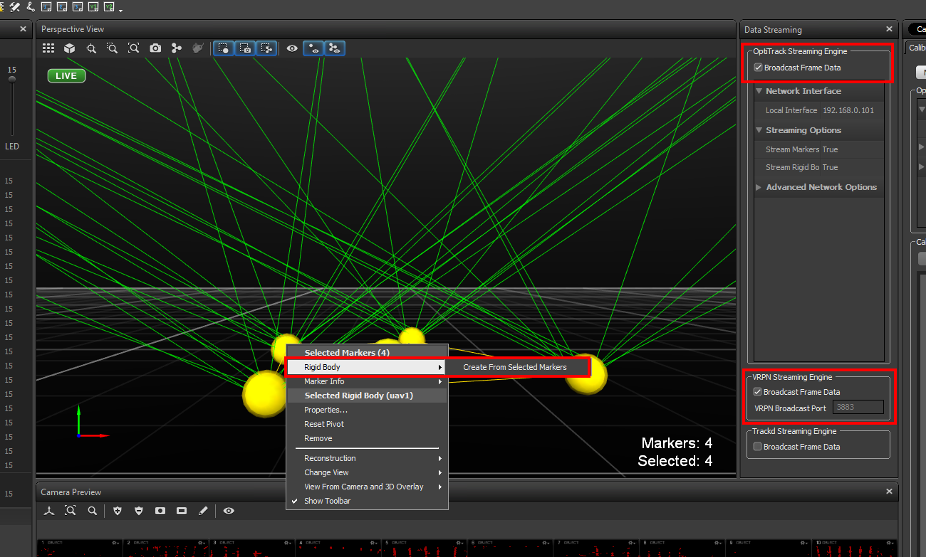
In Motive, choose View > Data Streaming from menu bar. Check the boxes Broadcast Frame Data in OptiTrack Streaming Engine and VRPN Streaming Engine sections. Create a rigid body by selecting markers of interest. In Advanced Network Options section change Up Axis to Z Up.
Important
Align your robot’s forward direction with the the system +x-axis.
Make sure you either turn off the Windows Firewall or create outbound rules for the VRPN port (recommended).
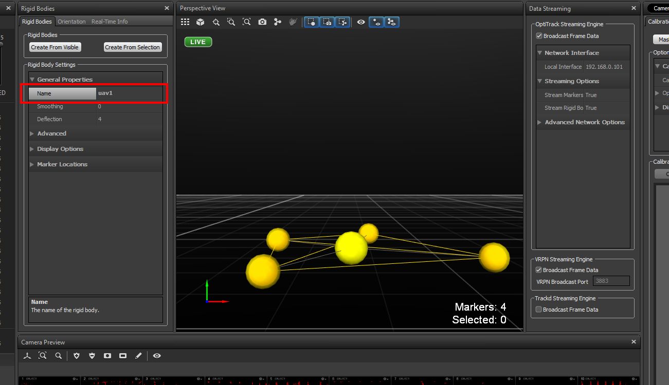
Right click on the body created, choose Properties and rename it such that there is no spaces in the name.
Streaming MOCAP Data
Check the IP address assigned to the Mocap machine, in our case it’s 192.168.0.101
On your odroid), where you want to get tracking data, run the vrpn_client_ros node as follows
roslaunch vrpn_client_ros sample.launch server:=192.168.0.101
Now you should be able to receive Mocap data under topic /vrpn_client_node/<rigid_body_name>/pose.
Open new terminal (CTRL + ALT + F2/F3/F3…) and try following command
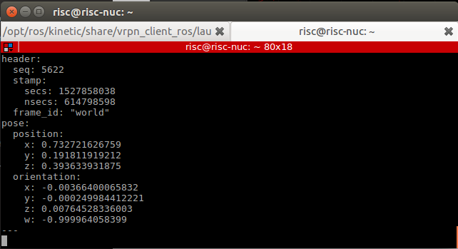
rostopic echo vrpn_client_node/<rigid_body_name>/pose
You should get similar to this. More information on message type here.
Feeding MOCAP data to Pixhawk

Intro
This tutorial shows you how to feed MOCAP data to Pixhawk that is connected to an ODROID, or an on-board linux computer. This will allow Pixhawk to have indoor position and heading information for position stabilization.
Hardware Requirements
- Pixhawk or similar controller that runs PX4 firmware
- ODROID (we will assume XU4)
- Serial connection, to connect ODROID to Pixhawk. You will need to solder you own USB/FTDI cable to connect from Odroid USB port to
TELEM2port on Pixhawk. Mind thatTXconnects toRX,RXconnects toTX,GtoG. If you are using MindPX flight controller, just use a USB to micro-USB cable and connect it to USB/OBC port. - OptiTrack PC
- WiFi router (5GHz is recommended)
Software Requirements
- Linux Ubuntu 16 installed on ODROID XU4. A minimal image is recommended for faster executions.
- ROS Kinetic installed on ODROID XU4. Already preinstalled in the image.
MAVROSpackage: Binary installation. Already preinstalled in the image.- Install
vrpn_client_rospackage. Already preinstalled in the image.
Now, you need to set your flight controller firmware PX4, to accept mocap data. EKF2 estimator can accept mocap data as vision-based data.
Settings in QGroundControl
To set up the default companion computer message stream on TELEM 2, set the following parameters:
If using firmware version below 1.9.0, change the following parameters:
SYS_COMPANION= Companion Link (921600 baud, 8N1)
Starting from firmware 1.9.0, change the following parameters:
MAV_1_CONFIG= TELEM 2 (MAV_1_CONFIG is often used to map the TELEM 2 port)MAV_1_MODE= OnboardSER_TEL2_BAUD= 921600 (921600 or higher recommended for applications like log streaming or FastRTPS)
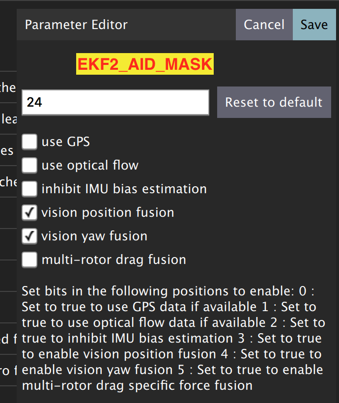
Set EKF2_AID_MASK to not use GPS, and use vision position fusion and vision yaw fusion.
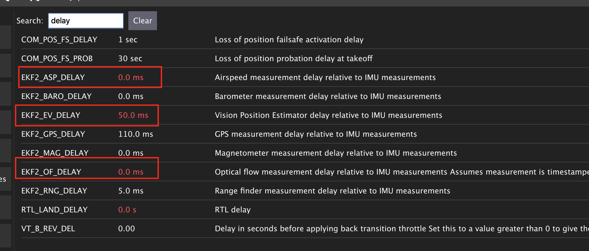
There are some delay parameters that need to set properly, because they directly affect the EKF estimation. For more information read this wiki
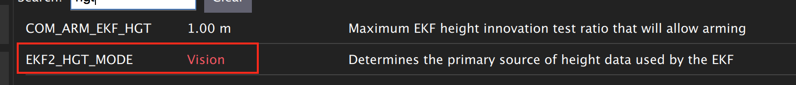
Choose the height mode to be vision
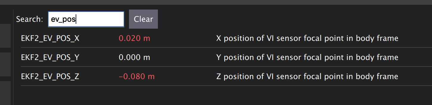
(OPTIONAL, for better accuracy). Set the position of the center of the markers (that define the rigid body in the mocap system) with respect to the center of the flight controller. +x points forward, +y right, +z down
Now Restart Pixhawk
Getting MOCAP data into PX4
Assuming your vrpn_client_node is still running from optitrack-interface on your ODROID, we will republish it to another topic by relay command.
You will need to run MAVROS node by openning a new separate terminal on ODROID (CTRL + ALT + F2/F3/F4)
roslaunch mavros px4.launch fcu_url:=/dev/ttyUSB0:921600 gcs_url:=udp://@192.168.0.105:14550
where fcu_url is the serial port that connects ODROID to the flight controller. Use ls /dev/ttyUSB* command on your Odroid to see if serial port is connected. Parameters gcs_url:=udp://@192.168.0.119:14550 is used to allow you to receive data to QGroundControl on your machine (that has to be connected to the same WiFi router). Adjust the IP to match your PC IP, that runs QGroundControl.
MAVROS provides a plugin to relay pose data published on /mavros/vision_pose/pose to PX4. Assuming that MAVROS is running, you just need to remap the pose topic that you get from Mocap /vrpn_client_node/<rigid_body_name>/pose directly to /mavros/vision_pose/pose.
rosrun topic_tools relay /vrpn_client_node/<rigid_body_name>/pose /mavros/vision_pose/pose
Check whether if you can switch your drone to Position mode (will be reported in QGroundControl). If successfull, you are ready to use position hold/offboard modes.
Check this page before first flight in Position mode.
Flying
Intro
Now it’s time to fly your drone in the cage!
We will need a PC running Linux with Joystick connected to it. To establish ODROID communication with that PC, we will setup ROS Network. The Odroid on the drone will be the ROS Master. The logic is the same as in the Software in the Loop simulator. The joystick commands will be converted to position setpoints and will be published to /mavros/setpoint_raw/local node. Finally MAVROS will send setpoints to autopilot (real flight controller on your drone).
Setup a ROS Network
- First let’s tell NUC/laptop running Linux that Odroid is the Master in the ROS network by editing
.bashrcfile. Open terminal and open.bashrcfile for editing.
gedit ~/.bashrc
- Add following lines to the end of the file. Just change last numbers to corresponding IP numbers.
export ROS_MASTER_URI=http://192.168.0.odroid_ip_number:11311
export ROS_HOSTNAME=192.168.0.pc_ip_number
Make sure you source the .bashrc file after this.
- From NUC/laptop log into an ODROID to get access to a command-line over a network. We will setup an Odroid as a Master now.
ssh odroid@192.168.0.odroid_ip_number
It will prompt to enter password, if you use minimal image provided then it’s odroid.
- Let’s edit
.bashrcfile on ODROID as well.
nano .bashrc
- Add the following lines to the end of the file. Just change last numbers to corresponding IP numbers.
export ROS_MASTER_URI=http://192.168.0.odroid_ip_number:11311
export ROS_HOSTNAME=192.168.0.odroid_ip_number
To save file, press Ctrl+X, press Y, hit Enter. Source the .bashrc file.
ODROID commands
- Run on ODROID separate terminals
vrpn_client_ros,MAVROSand relay.
roslaunch vrpn_client_ros sample.launch server:=192.168.0.101
roslaunch mavros px4.launch fcu_url:=/dev/ttyUSB0:921600 gcs_url:=udp://@192.168.0.pc_ip_number:14550
rosrun topic_tools relay /vrpn_client_node/<rigid_body_name>/pose /mavros/vision_pose/pose
NUC/laptop commands
It’s important at this stage to check if data from Mocap is published to /mavros/vision_pose/pose and /mavros/local_position/pose by echo’ing these topics.
- Download
joystick_flight.launchandsetpoints_node.pyfiles to the NUC/laptop and put them intoscriptsandlaunchfolder accordingly. Find and understand what’s different from code in SITL files.
# Inside the scripts folder of your package
wget https://raw.githubusercontent.com/risckaust/risc-documentations/master/src/indoor-flight/setpoints_node.py

#Inside the launch folder of your package
wget https://raw.githubusercontent.com/risckaust/risc-documentations/master/src/indoor-flight/joystick_flight.launch
- Make sure you give permissions to the joystick.
Danger
Keep the transmitter nearby to engage the Kill Switch trigger in case something will go wrong.
- Now run in a new terminal on the NUC/laptop your launch file
roslaunch mypackage joystick_flight.launch
Joystick control
BUTTON 1 - Arms the quadcopter
BUTTON 3 - Switches quadcopter to OFFBOARD flight mode. It should takeoff after this.
BUTTON 2 - Lands the quadcopter
BUTTON 11 - Disarms the quadcopter
Enjoy your flight.