Rover Assembly
Basic principles
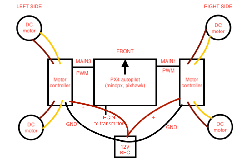
This tutorial will guide you how to build a skid-steer rover. Skid-steer vehicles have the wheels mechanically locked in synchronization on each side, and where the left-side drive wheels can be driven independently of the right-side drive wheels. We have to set skid-steer frame in flight controler’s configuration. The flight controller will generate PWM signal at MAIN PWM output ports. We will connect these ports to motor controller input (RC1 in this case). Then motor controller will drive the DC motors according to the signal coming from the flight controller. The following diagram shows how the system components connected together.
While building the rover, feel free to place the components anywhere inside the frame but take care of wires. Carefully choose zipties, shrinking tubes, double sided tapes or soldering for different situations.
Preliminaries
This tutorial assumes you have the following skills:
- ROS Basics.
- Soldering, if not, please refer to basic skill video.
- Basic knowledge about LiPo batteries. Answer the following questions. You may read this article.
- What do 3s, 4s mean?
- What does 20c mean?
- What does 1400mAh mean?
- What are the parameters of your battery?
- How to charge LiPo battery? How to measure it voltage using battery meter?
- What’s the minimum voltage to use a LiPo on the robot?
Danger
Do not leave your battery plugged in your robot for a long time and never discharge a LiPo battery below 3.4V per cell.
Hardware assembly
Introduction
You will need
- Rover frame with four wheels and DC motors.

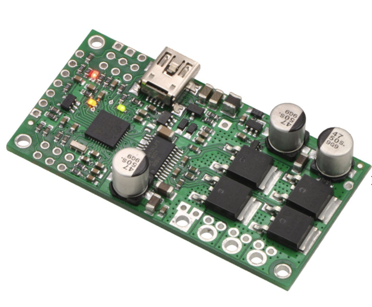
- Two motor controllers to control DC motors.
- Flight Controller. Use any flight controller available in the lab. Just make sure you have compatible power modules, receivers, GPS, and other additional modules. The documentations for each board are available here.
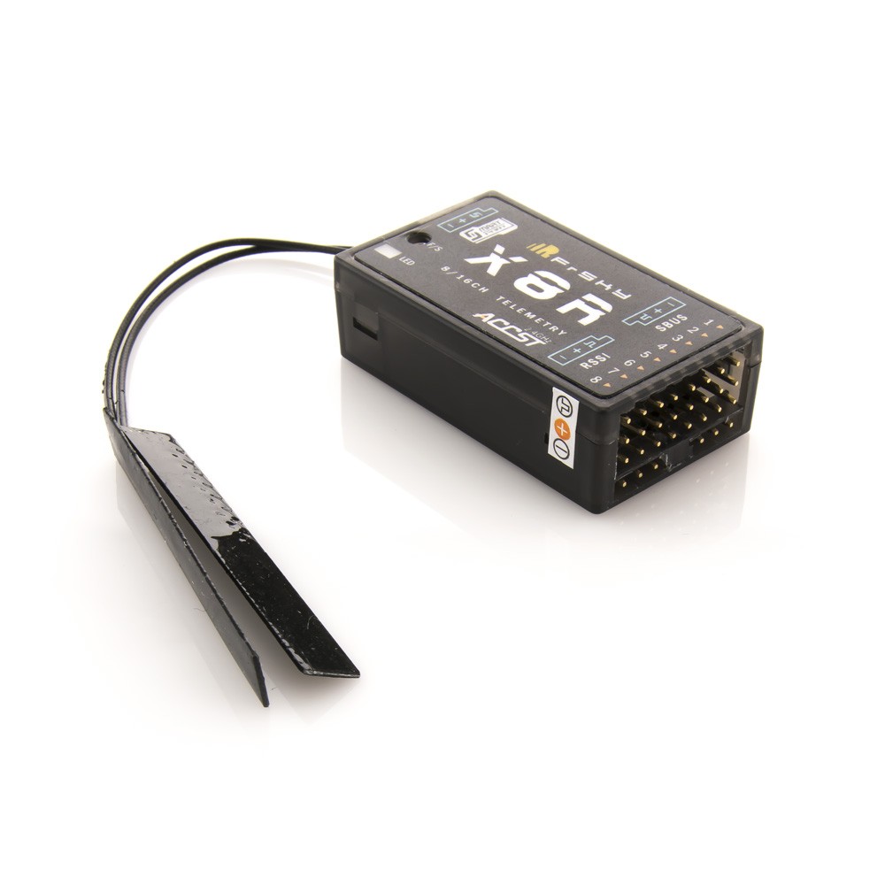
- Remote control system. A remote control (RC) radio system is required if you want to manually control your vehicle. In addition to the transmitter/receiver pairs being compatible, the receiver must also be compatible with PX4 and the flight controller hardware. It’s recommended to use Taranis X9D Plus transmitter with X8R receiver as shown below

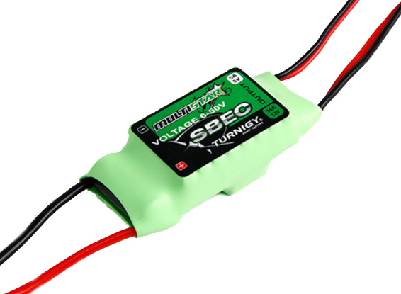
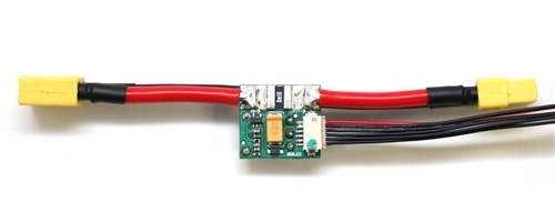
- UBEC (Universal Battery eliminator circuit) to convert voltage to power Odroid. A BEC is basically a step down voltage regulator. It will take your main battery voltage (e.g. 11.1 Volts) and reduce it down to 5/12 Volts to safely power your Odroid and other electronics. We will use Twin Output BEC which will power Odroid and Motor controllers at the same time.
- Power module. It is the best way to provide power for flight controller unit. It has voltage and current sensors that allows autopilot to estimate remaining battery charge precisely. Usually it comes with every autopilot controller as a default kit. Check official documentations to match right power module to a selected flight controller.
- LiPo battery. 3000/4000 mAh 3S battery is recommended.

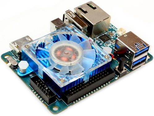
- Odroid XU4. Onboard computer that will run high level programs and algorithms. It will be connected to Flight Controller through serial connection. Odroid will need WiFi USB module, eMMC memory module and DC Plug Cable.
Assembly process
- Install DC motors to the frame if necessary. Attach the wheels to the motor shafts with provided screw sets.
- Attach flight controller on the frame. Take a look at your flight controller and make sure the arrow is pointing to the front. To mount the controller to the frame, use thick double side tape to damp the vibrations.
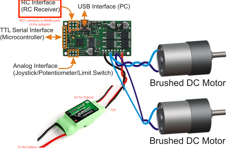
- Connect right side motor’s red cable to OUTB, and yellow cable to to the OUTA of the first motor controller. The motor controller’s RC1 port should be connected to MAIN1 PWM ouput channel. Make sure you match SIGNAL, + and -. Use servo cable for this connection.
- Connect left side motor’s red cable to OUTA, and yellow cable to to the OUTB of the second motor controller. The motor controller’s RC1 port should be connected to MAIN3 PWM ouput channel. Again match SIGNAL, + and -.
- Connect BEC’s 12V positive and ground outputs to VIN and GND respectively. You have to connect both motor controllers. They will be powered from the same BEC.
The following diagram shows the connection for one of the sides. RC Interface (RC Receiver) is used for connecting to flight controller. USB Interface is used for modifying settings on the motor controller and flashing firmware.
Install power module on the frame. Plug cable from power module to
POWERport of your flight controller.Plug buzzer and switch to their corresponding ports on flight controller.
Connect the
RCINport from Pixhawk toSBUSport on X8R and follow the binding process for FrSky X8R.- Turn on the X8R while holding the F/S button on the module. Release the button.
- Press the Menu button on your Taranis X9D transmitter.
- Go to page 2 by pressing Page button.
- Scroll down with - button until you see Internal RF line.
- Select [Bind] line, and press ENT button. The RED LED on the X8R receiver will flash, indicating the binding process is completed
Calibration process
- Open QGroundControl and connect your flight controller to the computer.
- Install Stable PX4 firmware.
- Set the airframe to Axial Racing AX10. Follow steps from this page.
- Calibrate Compass, Accelerometer, and Level Horizon.
- Calibrate the Radio.
- In
Flight Modestab under the Flight Mode Settings and Switch settings sections set:- Mode Channel to SB (SB switch labeled on your Taranis X9D)
- Mode 1: Manual.
- Mode 4: Altitude. Climb and drop are controlled to have a maximum rate.
- Mode 6: Position. When sticks are released the vehicle will stop and hold position.
- Emergency Kill switch channel to SF (SF switch labeled on your Taranis X9D). Immediately stops all motor outputs. The vehicle will crash, which may in some circumstances be more desirable than allowing it to continue flying.
- Offboard switch channel to SA (SA switch labeled on your Taranis X9D).
You should have similar as shown in the picture below. Channels for Flight Mode Settings and Switch Settings might differ.

Hint
If you set everything right, you will see changes in Flight Mode Settings section highlighted as yellow. Also, moving sticks, dials and switches will be reported in Channel Monitor section.
- In
Power tabwrite the parameters of your battery (Number of cells), calibrate the battery voltage.- Press Calculate on the Voltage divider line.
- Measure the voltage with Digital Battery Capacity Checker by connecting it to the battery.
- Enter the the voltage value from the Digital Battery Capacity Checker and press Calculate button.
- Search for
FW_ARSP_MODEin QGroundControl parameters, and set it to Airspeed disabled. - Search for
PWM_MAXandPWM_MINand set them to 2200 and 800 respectively.
Configuring the motor controller
Download Simple Motor Controller Linux Software on the Ubuntu based computer. Open terminal and navigate to the downloaded folder, and unzip the archive with the following command.
tar -xzvf smc-linux-101119.tar.gz #File name might differ
After following the instructions in README.txt , you can run the program by following command.
./SmcCenter
Connect motor controller to the Ubuntu based computer using mini USB cable. Navigate to Input Settings tab and change Input Mode to RC as shown below. After that press Apply Settings.

Driving the rover with the transmitter
- Make sure you switch Kill switch to off. Select Manual as your flight mode.
- Check the battery level, make sure it’s enough to perform your first ride.
Important
Always check the battery before starting
- Put the rover in the cage.
- Left stick on the transmitter controls left wheels, while right stick controls left wheels. By moving two sticks in the same side (left or ride) will move rover either front or backward. If you move stick in a opposite direction from each other, that will make rover to turn around it’s own axis.
Markers installation
Attach four Motion Capture Markers to the Rigid Body Marker Base. Mount Rigid Body Marker Base on the rover.